Description
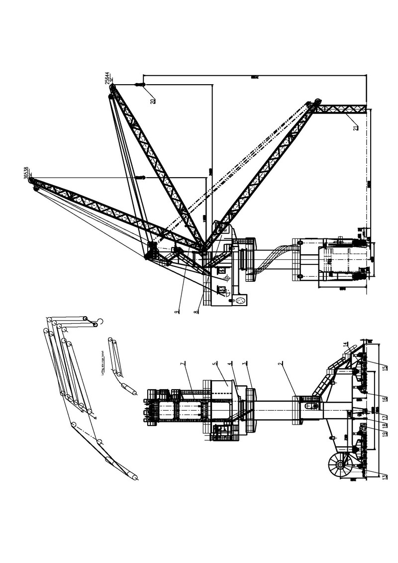
Single Boom Floating Dock Crane, also called “Level luffing floating dock crane or Portal jib crane” is mainly used on floating dock to lifting ship parts for ship construction and repair in shipyard. The crane has lifting mechanism, luffing mechanism,slewing mechanism and crane traveling mechanism.Lifting mechanism, luffing mechanism and slewing mechanism could work independently or work together. The upper rotation part of the crane supported above the gantry frame,can rotate 360°. The upper rotation parts is composed of boom, slewing platform, upper revolving column, machine room, cabin and so on. It is made up of hoisting mechanism, luffing mechanism and rotating mechanism. And the lower traveling part includes gantry frame,power system,traveling system, anchor device, anti-dumping hook device, wind-resistant cable and other components. Boom beam adopt on the steel pipe welded truss structure, light weight and wind area and wind coefficient is small, so the whole weight is light. The hinge point of the boom system adopts rolling bearing, the whole machine adopts electric centralized lubrication system and manual segmented centralized lubrication two ways. Lubrication of the slewing ring adopts electric centralized lubrication. The lubrication of the A-Bracket and the head pulley of the boom, the arm hinge and the walking mechanism is centralized lubrication by manual segmentation. Hook lubrication points on the used of artificial oil tanker lubrication. In the term of safety facilities, each system are equipped with limit protection and interlock with PLC to ensure the gantry crane safe work , but also with overload limit torque protection device, amplitude indicator, wind speed indicator, anti-climbing wedge and anti-typhoon anchor fixed devices and so on.Technical Parameter Table
| Unit | MQ7518 | MQ1020 | MQ1030 | MQ1524 | MQ2028 | ||
| Capacity | Ton | 7.5 | 10 | 10 | 15 | 20 | |
| Working duty | A | A5 | A5 | A5 | A5 | A5 | |
| Working radius | M | 7.5-18 | 7-20 | 9-30 | 11-24 | 11-28 | |
| Lifting height above rail | M | 20 | 22 | 22 | 21.5 | 30 | |
| Lifting height below rail | M | -10 | -13 | -13 | -13.5 | 19 | |
| Speed | Lifting speed | m/min | 15 | 25 | 25 | 14 | 14 |
| Luffing speed | m/min | 15 | 25 | 25 | 14 | 14 | |
| Slewing speed | r/min | 0.8 | 1.2 | 1.2 | 0.8 | 0.6 | |
| Traveling speed | m/min | 20 | 20 | 20 | 26 | 26 | |
| End slewing radius | M | 7.50 | 4.8 | 5.1 | 6.4 | 7 | |
| Gauge× Base | M | 3.4×6.5 | 3.4×5 | 5×5 | 4×10.5 | 4.65x8 | |
| Max.wheel load | KN | 165 | 240 | 250 | 250 | 200 | |
| Wheel Qty. | PCS | 16 | 12 | 16 | 24 | 24 | |
| Heel/Trim | 3°/2° | 3°/2° | 3°/2° | 3°/2° | 3°/2° | ||
| Power source | 380V 50HZ 3Ph | ||||||
Features of Floating Dock Crane
1. Certified by ABS,BV,CCS or other IACS; 2. All mechanism design conforms to classification society standard requirement; 3. 360° slewing, wide working scope; 4. PLC control, AC frequency speed control, stable and reliable running; 5. Heel 3 °, Trim 2 °; 6. All parts such as motor,reducer,slewing bearing,brake,wire rope,electrics elements,cable etc.has IACS certificate; 7.Marine corrosion proof paint adopts HEMPEL, JOTUN international known brand paint;Outline drawing
